
Stainless Steel 317L Flanges are low-carbon and high-molybdenum austenitic flanges produced to meet the ASTM A182 F317L specifications, designed to be used in corrosive welding products where sensitization-free performance is needed, along with aggressive acid resistance. With carbon held at 0.03% maximum, UNS S31703 eliminates intergranular corrosion at weld zones entirely, removing the need for post-weld heat treatment in fabricated assemblies. Meanwhile, the increased molybdenum (3-4 %) content provides SS 317L with an ultimate edge in corrosion resistance in sulfuric acid, chloride-containing media and FGD (Flue Gas
Desulfurization) conditions. In line with NACE MR0175 / ISO 15156 sour service, these DIN 1.4438 stainless steel flanges are the specification of choice in chemical processing vessels, pulp and paper digesters, pharmaceutical equipment and food processing piping. Amardeep Steel offers SS 317L flanges in 1/2-48 inch across pressure classes 150 2500 3.1 Mill Test Certificates, and with an established record of export to the international marketplace.
Specification of Stainless Steel 317L Flanges
| Category | Specification Details |
|---|---|
| Manufacturing Standard | ASTM A182 / ASME SA182 |
| Dimensional Standards | ANSI/ASME B16.5, B16.47 (Series A & B), B16.48, BS 4504, BS 10, EN-1092, DIN |
| Standard Types | ANSI, ASME, BS, DIN, EN Flanges |
| Size Range | 1/2″ (15 NB) to 48″ (1200 NB) |
| Pressure Ratings (Class) | 150#, 300#, 600#, 900#, 1500#, 2500# |
| Pressure Ratings (PN) | PN6, PN10, PN16, PN25, PN40, PN64 |
| Flange Face Types | Flat Face (FF), Raised Face (RF), Ring Type Joint (RTJ) |
Chemical Properties of SS 317L Flanges
| Grade | C | Mn | Si | P | S | Cr | Mo | Ni | Fe |
|---|---|---|---|---|---|---|---|---|---|
| SS 317L | 0.035 max | 2.0 max | 1.00 max | 0.045 max | 0.030 max | 18.00 – 20.0 | 3.00 – 4.00 | 11.00 – 15.0 | 57.89 min |
ASTM A182 SS Flanges Mechanical Properties
| Tensile Strength (Min) | Yield Strength (0.2% Offset, Min) | Elongation (in 50mm, Min) | Hardness (Brinell, Max) | Hardness (Rockwell B, Max) |
|---|---|---|---|---|
| 515 MPa | 205 MPa | 35% | 217 HBW | 95 HRB |
Physical Properties of AISI 317L Blind Flanges
| Density | Melting Point | Tensile Strength | Yield Strength (0.2% Offset) | Elongation |
|---|---|---|---|---|
| 7.9 g/cm³ | 1400°C (2550°F) | 75,000 Psi (515 MPa) | 30,000 Psi (205 MPa) | 35% |
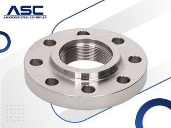
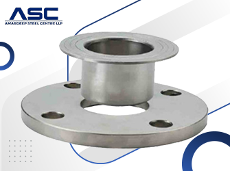
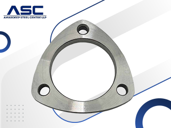
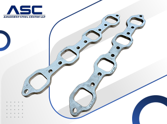
Types of Stainless Steel 317L Flanges
Dimensions Chart Of ASTM A182 F317L Flanges
| NPS | O (OD) | Q (Thk) | R (RF) | X (Hub) | Y (WN) | Y (SO/SW) | B (SO/SW) | B (Loose) | W (Bevel) | Hr (Rad) |
|---|---|---|---|---|---|---|---|---|---|---|
| 1/2″ | 3.50 | 7/16 | 1-3/8 | 1-3/16 | 1-7/8 | 5/8 | 0.88 | 0.90 | 0.84 | 1/8 |
| 3/4″ | 3.88 | 1/2 | 1-11/16 | 1-1/2 | 2-1/16 | 5/8 | 1.09 | 1.11 | 1.05 | 1/8 |
| 1″ | 4.25 | 9/16 | 2 | 1-15/16 | 2-3/16 | 11/16 | 1.36 | 1.38 | 1.32 | 1/8 |
| 1-1/4″ | 4.62 | 5/8 | 2-1/2 | 2-5/16 | 2-1/4 | 13/16 | 1.70 | 1.72 | 1.66 | 3/16 |
| 1-1/2″ | 5.00 | 11/16 | 2-7/8 | 2-9/16 | 2-7/16 | 7/8 | 1.95 | 1.97 | 1.90 | 1/4 |
| 2″ | 6.00 | 3/4 | 3-5/8 | 3-1/16 | 2-1/2 | 1 | 2.44 | 2.46 | 2.38 | 5/16 |
| 2-1/2″ | 7.00 | 7/8 | 4-1/8 | 3-9/16 | 2-3/4 | 1-1/8 | 2.94 | 2.97 | 2.88 | 5/16 |
| 3″ | 7.50 | 15/16 | 5 | 4-1/4 | 2-3/4 | 1-3/16 | 3.57 | 3.60 | 3.50 | 3/8 |
| 3-1/2″ | 8.50 | 15/16 | 5-1/2 | 4-13/16 | 2-13/16 | 1-1/4 | 4.07 | 4.10 | 4.00 | 3/8 |
| 4″ | 9.00 | 15/16 | 6-3/16 | 5-5/16 | 3 | 1-5/16 | 4.57 | 4.60 | 4.50 | 7/16 |
| 5″ | 10.00 | 15/16 | 7-5/16 | 6-7/16 | 3-1/2 | 1-7/16 | 5.66 | 5.69 | 5.56 | 7/16 |
| 6″ | 11.00 | 1 | 8-1/2 | 7-9/16 | 3-1/2 | 1-9/16 | 6.72 | 6.75 | 6.63 | 1/2 |
| 8″ | 13.50 | 1-1/8 | 10-5/8 | 9-11/16 | 4 | 1-3/4 | 8.72 | 8.75 | 8.63 | 1/2 |
| 10″ | 16.00 | 1-3/16 | 12-3/4 | 12 | 4 | 1-15/16 | 10.88 | 10.92 | 10.75 | 1/2 |
| 12″ | 19.00 | 1-1/4 | 15 | 14-3/8 | 4-1/2 | 2-3/16 | 12.88 | 12.92 | 12.75 | 1/2 |
| 14″ | 21.00 | 1-3/8 | 16-1/4 | 15-3/4 | 5 | 3-1/8 | 14.14 | 14.18 | 14.00 | 1/2 |
| 16″ | 23.50 | 1-7/16 | 18-1/2 | 18 | 5 | 3-7/16 | 16.16 | 16.19 | 16.00 | 1/2 |
| 18″ | 25.00 | 1-9/16 | 21 | 19-7/8 | 5-1/2 | 3-13/16 | 18.18 | 18.20 | 18.00 | 1/2 |
| 20″ | 27.50 | 1-11/16 | 23 | 22 | 5-11/16 | 4-1/16 | 20.20 | 20.25 | 20.00 | 1/2 |
| 24″ | 32.00 | 1-7/8 | 27-1/4 | 26-1/8 | 6 | 4-3/8 | 24.25 | 24.25 | 24.00 | 1/2 |
Thickness Chart of SS 317L Flanges
| NPS | O.D. | Sch 10 | Sch 40 / STD | Sch 80 / EH | Sch 120 | Sch 160 | XXH |
|---|---|---|---|---|---|---|---|
| 1/2″ | 0.840 | 0.083 | 0.109 | 0.147 | — | 0.188 | 0.294 |
| 3/4″ | 1.050 | 0.083 | 0.113 | 0.154 | — | 0.219 | 0.308 |
| 1″ | 1.315 | 0.109 | 0.133 | 0.179 | — | 0.250 | 0.358 |
| 1-1/4″ | 1.660 | 0.109 | 0.140 | 0.191 | — | 0.250 | 0.382 |
| 1-1/2″ | 1.900 | 0.109 | 0.145 | 0.200 | — | 0.281 | 0.422 |
| 2″ | 2.375 | 0.109 | 0.154 | 0.218 | — | 0.344 | 0.436 |
| 2-1/2″ | 2.875 | 0.120 | 0.203 | 0.276 | — | 0.375 | 0.552 |
| 3″ | 3.500 | 0.120 | 0.216 | 0.300 | — | 0.438 | 0.600 |
| 4″ | 4.500 | 0.120 | 0.237 | 0.337 | 0.438 | 0.531 | 0.674 |
| 6″ | 6.625 | 0.134 | 0.280 | 0.432 | 0.562 | 0.719 | 0.864 |
| 8″ | 8.625 | 0.148 | 0.322 | 0.500 | 0.719 | 0.906 | 0.875 |
| 10″ | 10.75 | 0.165 | 0.365 | 0.500 | 0.844 | 1.125 | 1.000 |
| 12″ | 12.75 | 0.180 | 0.375 | 0.500 | 1.000 | 1.312 | 1.000 |
| 14″ | 14.00 | 0.250 | 0.375 | 0.500 | 1.094 | 1.406 | — |
| 16″ | 16.00 | 0.250 | 0.375 | 0.500 | 1.219 | 1.594 | — |
| 18″ | 18.00 | 0.250 | 0.375 | 0.500 | 1.375 | 1.781 | — |
| 24″ | 24.00 | 0.250 | 0.375 | 0.500 | 1.812 | 2.344 | — |
Weight Chart of Stainless Steel 317L Flanges
| NPS | Slip-On (SORF) | Threaded (NPT) | Socket Weld (SWRF) | Lap Joint | Blind (BLRF) | Weld Neck (WNRF) |
|---|---|---|---|---|---|---|
| 1/2″ | 1 | 1 | 1 | 1 | 1 | 2 |
| 3/4″ | 2 | 2 | 2 | 2 | 2 | 2 |
| 1″ | 2 | 2 | 2 | 2 | 2 | 3 |
| 1-1/4″ | 3 | 3 | 3 | 3 | 3 | 3 |
| 1-1/2″ | 3 | 3 | 3 | 3 | 4 | 4 |
| 2″ | 5 | 5 | 5 | 5 | 5 | 6 |
| 2-1/2″ | 8 | 8 | 8 | 8 | 7 | 10 |
| 3″ | 9 | 9 | 9 | 9 | 9 | 11.5 |
| 3-1/2″ | 11 | 12 | 11 | 11 | 11 | 13 |
| 4″ | 13 | 13 | 13 | 13 | 17 | 16.5 |
| 5″ | 15 | 15 | 15 | 15 | 20 | 21 |
| 6″ | 19 | 19 | 19 | 19 | 27 | 26 |
| 8″ | 30 | 30 | 30 | 30 | 47 | 42 |
| 10″ | 43 | 43 | 43 | 43 | 70 | 54 |
| 12″ | 64 | 64 | 64 | 64 | 123 | 88 |
| 14″ | 90 | 90 | 90 | 105 | 140 | 114 |
| 16″ | 106 | 98 | 98 | 140 | 180 | 140 |
| 18″ | 130 | 130 | 130 | 160 | 220 | 165 |
| 20″ | 165 | 165 | 165 | 195 | 285 | 197 |
| 22″ | 185 | 185 | 185 | 245 | 355 | 225 |
| 24″ | 220 | 220 | 220 | 275 | 430 | 268 |
A182 Gr F317L Flange Size Chart
| Nom. Size | Dim | Class 125/150 | Class 300 | Class 400 | Class 600 | Class 900/1500 | Class 2500 |
|---|---|---|---|---|---|---|---|
| 1/2″ | A | 3 1/2″ | 3 3/4″ | 3 3/4″ | 3 3/4″ | 4 3/4″ | 5 1/4″ |
| b | 7/16″ | 9/16″ | 9/16″ | 9/16″ | 7/8″ | 1 3/16″ | |
| D2 | 1 3/8″ | 1 3/8″ | 1 3/8″ | 1 3/8″ | 1 3/8″ | 1 3/8″ | |
| D1 | 2 3/8″ | 2 5/8″ | 2 5/8″ | 2 5/8″ | 3 1/4″ | 3 1/2″ | |
| n-d | 4-5/8″ | 4-5/8″ | 4-5/8″ | 4-5/8″ | 4-7/8″ | 4-7/8″ | |
| 3/4″ | A | 3 7/8″ | 4 5/8″ | 4 5/8″ | 4 5/8″ | 5 1/8″ | 5 1/2″ |
| b | 1/2″ | 5/8″ | 5/8″ | 5/8″ | 1″ | 1 1/4″ | |
| D2 | 1 11/16″ | 1 11/16″ | 1 11/16″ | 1 11/16″ | 1 11/16″ | 1 11/16″ | |
| D1 | 2 3/4″ | 3 1/4″ | 3 1/4″ | 3 1/4″ | 3 1/2″ | 3 3/4″ | |
| n-d | 4-5/8″ | 4-3/4″ | 4-3/4″ | 4-3/4″ | 4-7/8″ | 4-7/8″ | |
| 1″ | A | 4 1/4″ | 4 7/8″ | 4 7/8″ | 4 7/8″ | 5 7/8″ | 6 1/4″ |
| b | 9/16″ | 11/16″ | 11/16″ | 11/16″ | 1 1/8″ | 1 3/8″ | |
| D2 | 2″ | 2″ | 2″ | 2″ | 2″ | 2″ | |
| D1 | 3 1/8″ | 3 1/2″ | 3 1/2″ | 3 1/2″ | 4″ | 4 1/4″ | |
| n-d | 4-5/8″ | 4-3/4″ | 4-3/4″ | 4-3/4″ | 4-1″ | 4-1 1/4″ | |
| 1 1/4″ | A | 4 5/8″ | 5 1/4″ | 5 1/4″ | 5 1/4″ | 6 1/4″ | 7 1/4″ |
| b | 5/8″ | 3/4″ | 13/16″ | 13/16″ | 1 1/8″ | 1 1/2″ | |
| D2 | 2 1/2″ | 2 1/2″ | 2 1/2″ | 2 1/2″ | 2 1/2″ | 2 1/2″ | |
| D1 | 3 1/2″ | 3 7/8″ | 3 7/8″ | 3 7/8″ | 4 3/8″ | 5 1/8″ | |
| n-d | 4-5/8″ | 4-3/4″ | 4-3/4″ | 4-3/4″ | 4-1″ | 4-1 1/8″ | |
| 1 1/2″ | A | 5″ | 6 1/8″ | 6 1/8″ | 6 1/8″ | 7″ | 8″ |
| b | 11/16″ | 13/16″ | 7/8″ | 7/8″ | 1 1/4″ | 1 3/4″ | |
| D2 | 2 7/8″ | 2 7/8″ | 2 7/8″ | 2 7/8″ | 2 7/8″ | 2 7/8″ | |
| D1 | 3 7/8″ | 4 1/2″ | 4 1/2″ | 4 1/2″ | 4 7/8″ | 5 3/4″ | |
| n-d | 4-5/8″ | 4-7/8″ | 4-7/8″ | 4-7/8″ | 4-1 1/8″ | 4-1 1/4″ | |
| 2″ | A | 6″ | 6 1/2″ | 6 1/2″ | 6 1/2″ | 8 1/2″ | 9 1/4″ |
| b | 3/4″ | 7/8″ | 1″ | 1″ | 1 1/2″ | 2″ | |
| D2 | 3 5/8″ | 3 5/8″ | 3 5/8″ | 3 5/8″ | 3 5/8″ | 3 5/8″ | |
| D1 | 4 3/4″ | 5″ | 5″ | 5″ | 6 1/2″ | 6 3/4″ | |
| n-d | 4-3/4″ | 8-3/4″ | 8-3/4″ | 8-3/4″ | 8-1″ | 8-1 1/8″ | |
| 2 1/2″ | A | 7″ | 7 1/2″ | 7 1/2″ | 7 1/2″ | 9 5/8″ | 10 1/2″ |
| b | 7/8″ | 1″ | 1 1/8″ | 1 1/8″ | 1 5/8″ | 2 1/4″ | |
| D2 | 4 1/8″ | 4 1/8″ | 4 1/8″ | 4 1/8″ | 4 1/8″ | 4 1/8″ | |
| D1 | 5 1/2″ | 5 7/8″ | 5 7/8″ | 5 7/8″ | 7 1/2″ | 7 3/4″ | |
| n-d | 4-3/4″ | 8-7/8″ | 8-7/8″ | 8-7/8″ | 8-1 1/8″ | 8-1 1/4″ |
Pressure Rating Chart of SS 317L Flanges
| Temperature (°F) | Class 150 | Class 300 | Class 400 | Class 600 | Class 900 | Class 1500 | Class 2500 |
|---|---|---|---|---|---|---|---|
| -20 to 100 | 275 | 720 | 960 | 1440 | 2160 | 3600 | 6000 |
| 200 | 230 | 600 | 800 | 1200 | 1800 | 3000 | 5000 |
| 300 | 205 | 540 | 720 | 1080 | 1620 | 2700 | 4500 |
| 400 | 190 | 495 | 660 | 995 | 1490 | 2485 | 4140 |
| 500 | 170 | 465 | 620 | 930 | 1395 | 2330 | 3880 |
| 600 | 140 | 435 | 580 | 875 | 1310 | 2185 | 3640 |
| 650 | 125 | 430 | 575 | 860 | 1290 | 2150 | 3580 |
| 700 | 110 | 425 | 565 | 850 | 1275 | 2125 | 3540 |
| 750 | 95 | 415 | 555 | 830 | 1245 | 2075 | 3460 |
| 800 | 80 | 405 | 540 | 805 | 1210 | 2015 | 3360 |
| 850 | 65 | 395 | 530 | 790 | 1190 | 1980 | 3300 |
| 900 | 50 | 390 | 520 | 780 | 1165 | 1945 | 3240 |
| 950 | 35 | 380 | 510 | 765 | 1145 | 1910 | 3180 |
| 1000 | 20 | 320 | 430 | 640 | 965 | 1605 | 2675 |
| 1050 | 20 | 310 | 410 | 615 | 925 | 1545 | 2570 |
| 1100 | 20 | 255 | 345 | 515 | 770 | 1285 | 2145 |
| 1150 | 20 | 200 | 265 | 400 | 595 | 995 | 1655 |
| 1200 | 20 | 155 | 205 | 310 | 465 | 770 | 1285 |
| 1300 | 20 | 85 | 115 | 170 | 255 | 430 | 715 |
| 1400 | 20 | 50 | 65 | 95 | 145 | 240 | 400 |
| 1500 | 20 | 25 | 35 | 55 | 80 | 135 | 230 |
Application and Industrial Uses of Stainless Steel 317L Flanges
- Oil And Gas Industry
- Municipal Pipe Systems
- Food Processing And
- Manufeccessing
- Fossil Fuel Power Plants
- Waterworks Systems
- Nuclear Power Application
- Nuclear Power Application
- Power Plants Industry
Related Products
- Stainless Steel 304 Flanges
- Stainless Steel 304L Flanges
- Stainless Steel 304H Flanges
- Stainless Steel 310 Flanges
- Stainless Steel 310S Flanges
- Stainless Steel 316 Flanges
- Stainless Steel 316L Flanges
- Stainless Steel 316H Flanges
- Stainless Steel 317 Flanges
- Stainless Steel 317L Flanges
- Stainless Steel 321 Flanges
- Stainless Steel 321H Flanges
- Stainless Steel 347 Flanges
- Stainless Steel 347H Flanges
- Stainless Steel 446 Flanges
Frequently Asked Questions
What is Stainless Steel 317L flange?
A Stainless Steel 317L flange is a low-carbon, molybdenum-rich stainless steel pipe fitting known for excellent corrosion resistance and suitability for welded applications.
What is ASTM A182 F317L flange specification?
ASTM A182 F317L is a standard specification for forged stainless steel flanges designed for high-temperature and corrosion-resistant industrial use.
Why is SS 317L preferred for welding applications?
SS 317L is preferred for welding because its low carbon content prevents carbide precipitation, reducing the risk of corrosion in welded areas.
What is the pressure rating of ASTM A182 F317L flanges?
ASTM A182 F317L flanges are available in pressure classes from 150# to 2500#, depending on size and design standards like ASME B16.5.
Does SS 317L require post-weld heat treatment (PWHT)?
No, SS 317L typically does not require post-weld heat treatment because its low carbon content prevents sensitization.
